Dashboard Electronics Repair Guide for UK Drivers
A speedometer that drops to zero, a flickering LCD display or warning lights that vanish when you need them is more than an annoyance. Your instrument cluster is a safety-critical part of the vehicle, and a fault can also lead to an MOT concern, a failed journey or an incorrect diagnosis elsewhere. This dashboard electronics repair guide explains what commonly goes wrong, what to check first and when a specialist repair is the sensible alternative to replacing the whole unit.
What your dashboard is actually telling you
Modern dashboards, often called instrument clusters, do far more than display speed and fuel level. They receive information from multiple vehicle systems, process it through internal electronics and show the driver essential warnings. Depending on the vehicle, the cluster may also store mileage, immobiliser data, coding and service information.
That is why a fault can appear in several ways. One gauge may stop working while the rest of the dashboard appears normal. The LCD may lose pixels or become dim. Warning lights may flicker, stay permanently illuminated or fail to appear during the ignition check. In more serious cases, the whole cluster can go blank, repeatedly reboot or cause communication faults on diagnostic equipment.
The visible symptom does not always identify the failed component. A dead speedometer, for example, may be caused by a cluster motor fault, a power or earth issue, a vehicle speed signal problem or a communication fault elsewhere on the network. Proper diagnosis matters before anyone orders parts.
Dashboard electronics repair guide: start with sensible checks
Before removing the dashboard or assuming the cluster has failed, establish whether the fault is isolated, intermittent or linked to another electrical problem. A brief, methodical check can save time and prevent a good unit being sent away unnecessarily.
First, consider when the fault occurs. Does the display fail only when cold, after the vehicle has warmed up, over bumps or after heavy rain? Intermittent behaviour often points towards failing solder joints, ageing components or a connection issue. A fault that is present at every start-up may be more consistent with an internal power supply or processor problem.
Check the vehicle battery condition and charging voltage. Low voltage can cause strange warning messages, reset clocks and trip multiple dashboard alerts. If the battery is weak or the alternator is overcharging, resolve that issue first. A repaired cluster should not be refitted into a vehicle with an unresolved electrical supply fault.
Look for related symptoms too. Central locking, electric windows, infotainment and starting problems may indicate a wider power, earth or control-module issue rather than a dashboard-only failure. If only the instrument panel is affected, especially where a known display or gauge fault is present, the cluster itself becomes the more likely cause.
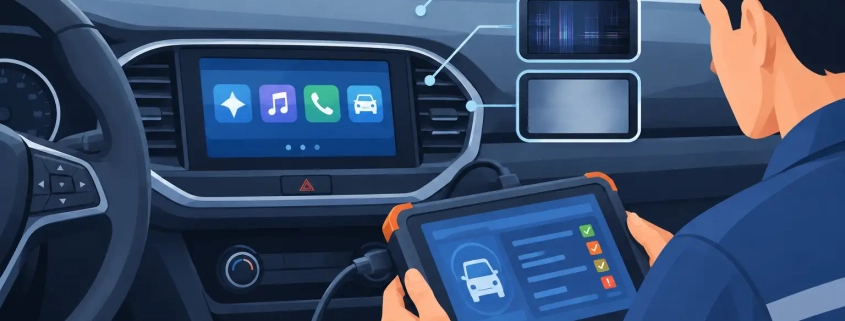
For garages and technicians, a full diagnostic scan is valuable, but fault codes need interpreting rather than simply clearing. A no-communication code could arise from the instrument cluster, wiring, connectors, a fuse or a network fault. Live data can help establish whether the vehicle is generating the correct speed, fuel or temperature information before the cluster is condemned.
Common instrument cluster faults
Pixel loss, fading screens and failed LCD displays
Missing pixels are particularly common on older and early modern digital displays. You may still be able to make out parts of the mileage, outside temperature, radio information or warning messages, but the display becomes difficult to read in daylight. Some screens fade when warm, then return temporarily after the car has cooled.
The repair may involve replacing or rebuilding the display assembly and its connections. Simply pressing on the screen or attempting a home repair can damage the ribbon connections and turn a repairable fault into a more expensive job. The right solution depends on the cluster design and availability of quality replacement components.
Inoperative or inaccurate gauges
Speedometers, rev counters, fuel gauges and temperature gauges can stick, jump, read inaccurately or remain at zero. On many clusters, small stepper motors or their associated circuitry wear out. A fuel gauge issue can also be caused by a sender unit in the tank, so diagnosis must distinguish between a signal problem and a gauge problem.
A specialist can test the cluster on dedicated equipment or an emulator. This allows the unit to be assessed away from the vehicle and helps confirm whether the gauge responds correctly to controlled inputs.
Warning light faults
Dim, failed or permanently lit warning lights deserve attention. If an indicator, main beam, engine management, ABS or airbag light does not illuminate at ignition-on, you may not receive a vital warning when a real fault develops. Conversely, a warning that remains lit is not automatically a dashboard defect – it may be reporting a genuine fault stored in another system.
Cluster repairs can address failed illumination, LED or backlight issues and internal display faults. They should not be used to hide a genuine safety-related warning. Any underlying ABS, airbag or engine fault still needs correct diagnosis and repair.
Complete cluster failure or repeated resetting
A blank instrument panel, flashing needles or a dashboard that repeatedly resets can be caused by internal power supply faults, failed components or damaged circuit-board connections. Water ingress, jump-starting errors and voltage spikes can all contribute.
This is where replacement can become costly. A new unit may require coding, mileage configuration and immobiliser programming, and it may not be available quickly. Repairing the original cluster is often preferable when the fault is repairable because the vehicle retains its original mileage and coding.
Why original-unit repair is often the better option
Replacing an instrument cluster is not always wrong. If the casing is severely damaged, the circuit board is beyond repair or a suitable repair is unavailable, replacement may be necessary. But it should not be the default answer for a display, gauge or common electronic fault.
Original-unit repair has clear advantages. It can avoid main dealer replacement costs and the delay of sourcing, programming and adapting a new cluster. It also retains the vehicle’s original data where applicable, reducing the risk of coding complications. For owners, that means less disruption. For garages, it means a clearer route to completing a job without sending the customer towards an unnecessary replacement bill.
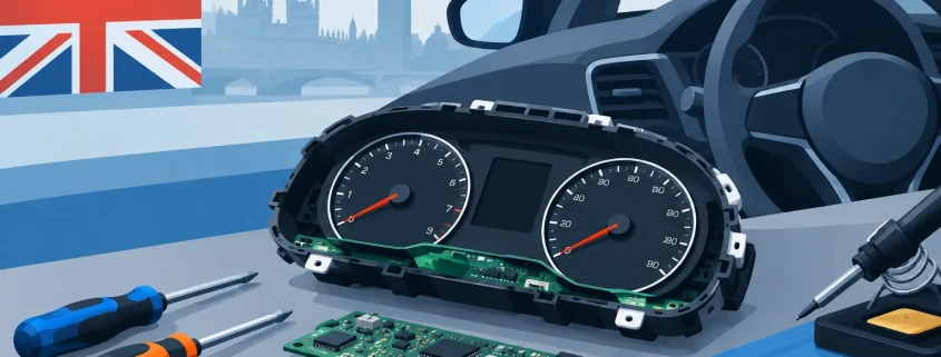
The quality of the repair process matters. A proper specialist service identifies the fault, repairs the board or components using appropriate equipment, tests the unit under simulated conditions and returns it ready for refitting. A warranty provides useful protection, but accurate initial diagnosis is still the foundation of a successful repair.
Avoid these costly mistakes
Do not swap a used cluster into the vehicle simply to see whether it works unless you fully understand the coding and security implications. On many vehicles, a replacement unit can create immobiliser, mileage or communication issues. It may also introduce faults of its own.
Avoid using stop-gap fixes such as striking the dashboard, repeatedly disconnecting the battery or applying pressure to a failing display. These actions may make an intermittent fault appear to improve for a short time, but they do not repair the underlying issue and can complicate diagnosis.
When posting a cluster for repair, package it carefully and include the vehicle make, model, year, engine type, part number and a clear description of the fault. Details such as whether the problem occurs only when warm or whether other vehicle functions are affected can significantly speed up testing.
When to book specialist dashboard repair
Specialist repair is the right next step when the vehicle has a confirmed or strongly suspected instrument cluster fault, particularly pixel loss, failed gauges, dim illumination, blank displays or intermittent operation. It is also useful where general diagnostic work has not resolved a communication issue and the cluster needs bench testing.
Cartronix repairs original instrument clusters for a wide range of vehicles from 1996 onwards, with postal repairs nationwide and while-you-wait workshop appointments where suitable. The aim is straightforward: diagnose the actual fault, retain the original unit where possible and get the vehicle back on the road without unnecessary dealer replacement costs.
If your dashboard has started behaving differently, act before a small display or gauge issue becomes a complete failure. A clear fault description and early specialist assessment usually give you the fastest route back to a dashboard you can rely on.